1Build one ladder
Join two 2200 mm posts with eight 204 mm rungs. Repeat until you have four ladders.
Revised final design · IMG 4486 wall · 1 August 2026
The lower-cost design leaves the useful white bookcase exactly where it is and adds a three-bay, open-backed solid-pine unit between it and the door—almost three ordinary bookcases of new capacity.
01 · Revised decision
The earlier full-wall proposal optimized one number—new shelf metres—and treated relocation as free. That was the wrong priority. The existing 790 mm bookcase already stores books, has no obvious new home and costs nothing to keep.
Eight shelf boards instead of eleven, while the existing unit continues working.
Three short bays and eight shelf surfaces, less the switch access slot.
No blocked hatch, displaced furniture or speculative second location.
Build from the right edge of the white shelf to the door. The measured opening is 1890 mm. Leave about 15 mm fitting clearance at both ends and make the new frame 1860 mm wide.
02 · Capacity comparison
Your measured bookcase is 790 mm wide with five shelf levels plus books on top: six usable surfaces. Capacity is compared as linear shelf frontage, because that maps most directly to the number of books.
| Storage | Calculation | Shelf metres |
|---|---|---|
| One measured wooden bookcase | 0.79 × 6 | 4.74 m |
| Two measured bookcases | 0.79 × 6 × 2 | 9.48 m |
| Three measured bookcases | 0.79 × 6 × 3 | 14.22 m |
| New three-bay unit | 0.556 × 3 × 8 − access | ≈13.1 m |
| New unit + retained white shelf | 13.1 + ≈4.7 | ≈17.8 m |
The new construction is 38% larger than two existing wooden units and only about 8% smaller than three. Keeping the white unit gives nearly the same total wall capacity as the expensive full-wall replacement.
03 · Rungs explained visually
A rung is not a shelf. It is a short 204 mm support rail connecting the front post to the rear post. Two posts plus eight rungs make one ladder-shaped side frame. Four of these ladder frames stand upright across the width of the bookcase. The long shelf boards lie left-to-right on top of matching rungs.
The simplest mental picture: build four narrow wooden ladders, stand them parallel like four bookends, then lay shelf boards across corresponding ladder rungs. The rungs are the ledges carrying the shelf boards.
You are standing at the end of the bookcase and looking along its width.
What you see: one front post, one rear post and the short rungs between them.
You are facing the books. Only the front post of each ladder is obvious.
What you see: four support stations and one continuous-looking shelf level.
You are looking down before books are loaded. The wall is at the top.
What you see: the 200 mm-deep shelf fits inside the 204 mm gap between rear and front posts.
Join two 2200 mm posts with eight 204 mm rungs. Repeat until you have four ladders.
Stand them parallel. Matching rungs must have exactly the same top height and be level.
Place 628 + 604 + 628 mm across the rungs. Together they make one 1860 mm shelf level.
Each joint must sit on the middle of a shared 48 mm rung: 24 mm supports the board on each side.
Drill a clearance hole through the shelf and a smaller pilot hole into the rung below.
Drive a 4 × 50 screw from the shelf top into the rung. Stop when the head is flush.
Nothing is floating. The shelf sits physically on the rung. The rung is screwed to both posts. The downward shelf screws prevent sliding and make the whole frame rigid; they are not carrying the book load by themselves.
04 · Room and dimensions
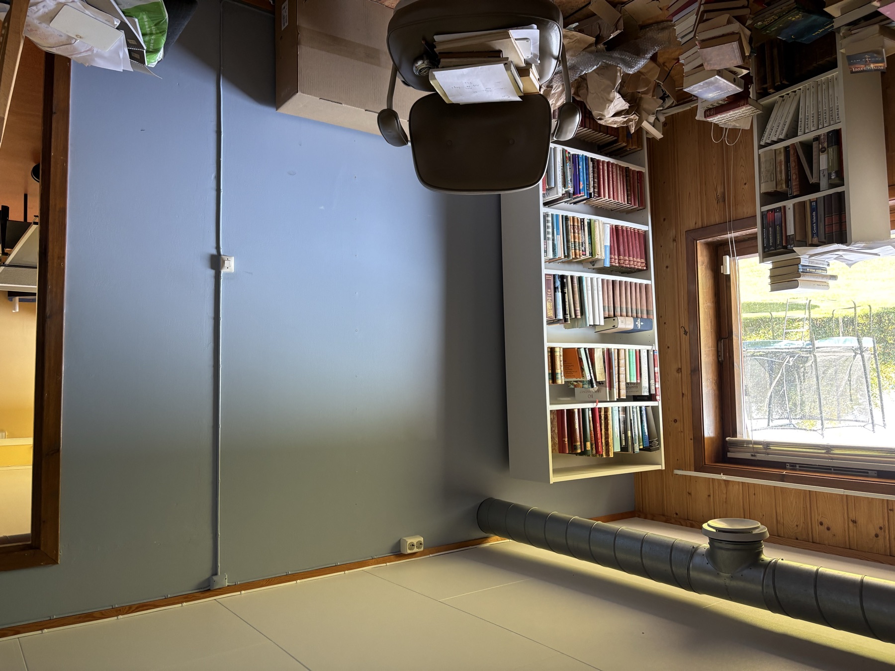
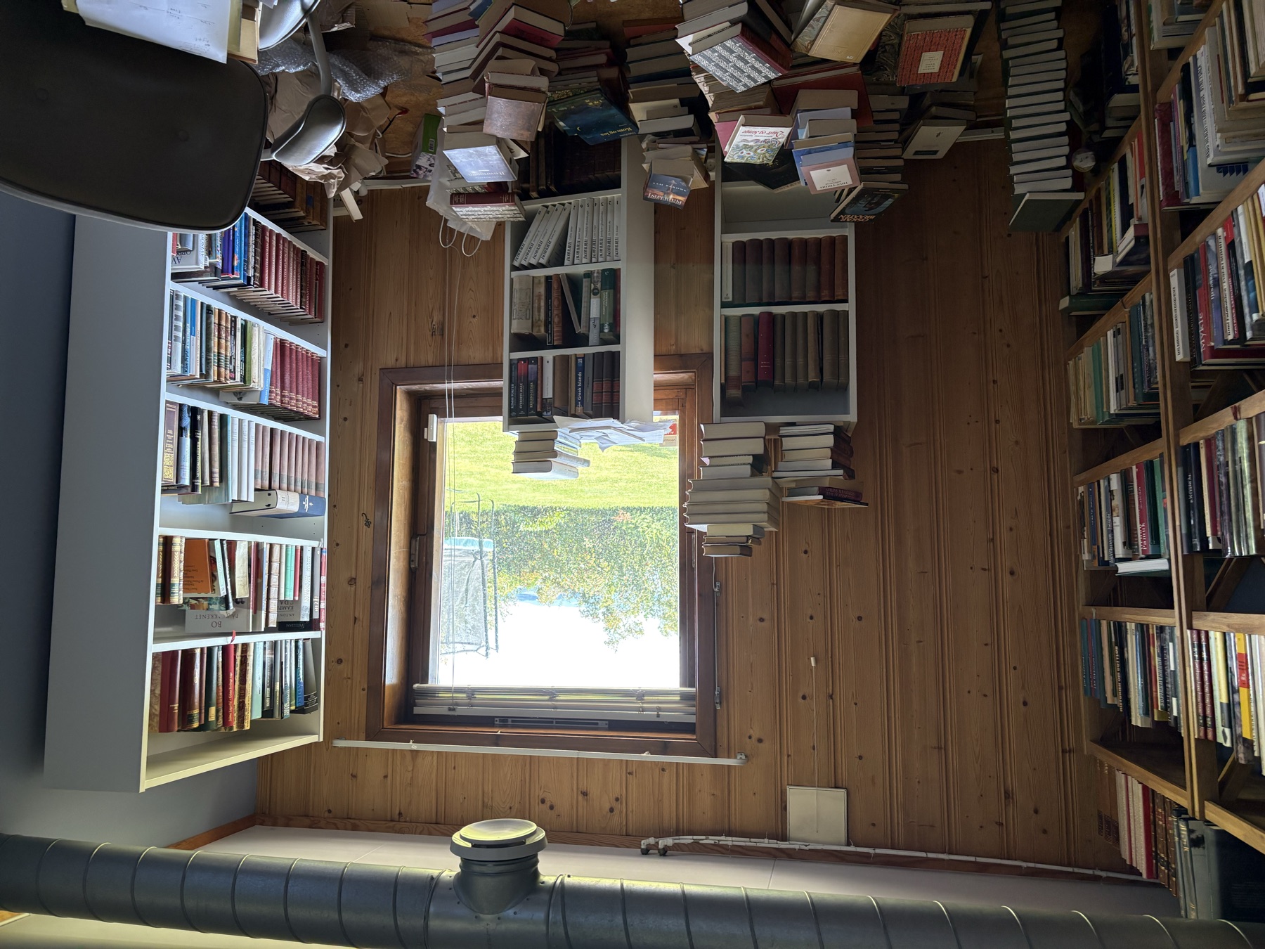
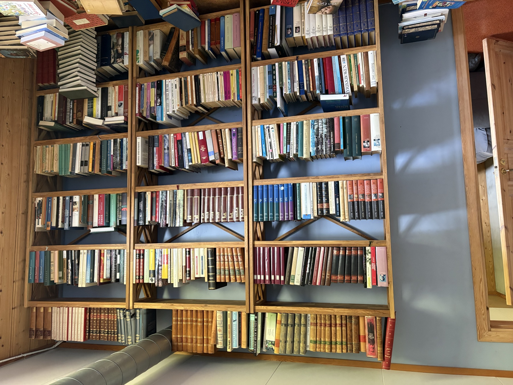
Ladder-frame left edges: 0, 604, 1208 and 1812 mm measured from the new unit’s left edge. Four 48 mm stations plus three 556 mm clear bays = 1860 mm.
The boards are 200 mm deep; the outside of the paired-post frame is 300 mm deep. The extra 4 mm inside the posts gives 2 mm fitting clearance at the front and rear of every shelf.
| Element | Size / position | Reason |
|---|---|---|
| Measured opening | 1890 mm | 1340 to switch + 50 switch + 500 to door |
| Finished new unit | 1860 × 2200 mm | About 15 mm fitting tolerance each end; 100 mm below ceiling |
| Clear bay | 556 mm | Short, stiff span for continuously loaded 18 mm pine |
| Rung-top heights | 70 / 390 / 700 / 990 / 1280 / 1570 / 1860 / 2020 | Eight shelf surfaces; shelf tops are 18 mm higher |
| Normal clear rows | 272–302 mm | Fits the dominant books visible in the room |
| Compact top row | 142 mm | Horizontal stacks and small books |
05 · Materials and exact cuts
| Material | Qty | Reference price | Subtotal | Use |
|---|---|---|---|---|
| 18 × 200 × 2000 mm gran/furu shelf board | 8 | 249 kr | 1,992 kr | 24 shelf pieces: one stock board per complete level |
| 48 × 48 × 4800 mm untreated class-1 lekt | 6 | 103 kr | 618 kr | 8 posts + 32 depth rungs |
| 9–18 mm plywood/OSB offcut + perforated strap | 4 panels + rear X | allow 250–500 | 250–500 | Side-frame shear panels and width-direction bracing |
| 5 × 100 TX25 partial-thread structural wood screws | 200 | allow 300–450 | 300–450 | 128 used at rung-to-post joints |
| 4 × 50 TX20 screws | 200 | allow 200–300 | 200–300 | Shelves and shear panels; strap screws must match the strap holes |
| D3 glue + wall-restraint hardware | — | allow 250–450 | 250–450 | Side ladders and mandatory anti-tip anchoring |
| Estimated structural total | ≈3,600–4,300 kr | Finish optional; use a cheap panel offcut if available |
At every height, install 628 + 604 + 628 mm. The two joints land on the centres of the shared 48 mm rungs. Confirm the finished 1860 mm width before cutting all eight boards.
| Part | Qty | Cut length | Label / note |
|---|---|---|---|
| Posts | 8 | 2200 mm | L1-front/rear through L4-front/rear |
| Depth rungs | 32 | 204 mm | Eight per ladder; outside frame depth becomes exactly 300 mm |
| Outer shelf pieces | 16 | 628 mm | Left and right piece at each level |
| Middle shelf pieces | 8 | 604 mm | One per level |
| Side shear panels | 4 | 300 × 200 mm | 9–18 mm plywood/OSB; two on each outer ladder |
| Rear X straps | 2 | Measure after squaring | Galvanised perforated strap with compatible pan-head/washered screws |
| Wall spacer blocks | At least 3 | 50 mm deep | Fit only at verified structural anchor locations |
Stock plan for the 48 × 48: four lengths each produce two 2200 mm posts and one 204 mm rung from the remainder. A fifth length produces about 23 rungs; the sixth produces the last five and leaves useful jig/spacer stock. Kerf and imperfect ends are why five lengths are not enough.
06 · Structural system
| Possible movement | Part that stops it | Connection |
|---|---|---|
| Shelf bends downward under books | 556 mm clear span + 18 mm solid pine | Each end bears on a 48 mm rung |
| Front posts lean relative to rear posts | Top and bottom shear panels on both outside ladders | Glue + six screws per panel |
| Whole unit leans left or right | Two rear straps forming an X | Strap screwed to all four rear posts |
| Whole unit tips into the room | At least three independent wall restraints | Verified stud/masonry anchors with rigid 50 mm spacers |
Load path: books → 18 mm shelf board → 204 mm rung at each end → paired 48 × 48 posts → floor. The screws stop parts sliding and racking; the shelf load itself is carried by wood bearing on wood, not by a screw hanging in empty space.
07 · How the two posts on each side are braced
2 × 5×100 into each rung end using the
staggered drilling template in the next section. Glue is
optional and is not counted as structural support at this
end-grain joint.
3 × 4×50 screws into
each post: six per panel. Put the screw line through the 24
mm centre of each post.
A panel is more beginner-proof than a shallow diagonal on a 300 mm-wide frame: it creates a rigid shear plate and cannot loosen because its angle was cut imperfectly.
If cheap panel offcuts are unavailable: use two perforated straps forming a complete X on the outside face of each end ladder. One strap alone works well in only one tension direction; the pair is required. Do not omit side bracing and assume the rear X performs the same job—it braces a different plane.
08 · Drill the rung-to-post joint
The final specification is a partially threaded 5 × 100 mm structural wood screw. It travels through the 48 mm post and approximately 52 mm into the 204 mm rung. Each rung has two ends, and each end receives two screws: four screws per rung.
Why 100 mm? A typical 5 × 100 ESSDRIVE screw has approximately 53 mm of thread and 47 mm of unthreaded shank. That closely matches the 48 mm post: the shank passes through the post while the thread grips the rung. The screw cannot reach the far post because the rung alone is 204 mm long.
You are looking straight at the 48 × 48 mm outside face of one post. The rung end is hidden immediately behind this square.
Hole A: 16 mm from the left edge and 15 mm below the rung top. Hole B: 16 mm from the right edge and 15 mm above the rung bottom—equivalently 33 mm below its top. The diagonal stagger avoids creating one straight split line.
Imagine slicing through the joint along the screw. The outside of the post is at left; the screw travels toward the rung.
The thread belongs in the rung, not mostly in the post. Buy partially threaded structural wood screws and check the actual thread length printed by the manufacturer.
Clamp the rung tightly between the two posts. Its top must match the story-stick line and its end must touch the post.
At A and B, drill a 4 mm clearance hole through only the 48 mm post. Use tape on the bit at approximately 48 mm.
Through the clearance hole, drill a 3 mm pilot to approximately 90 mm total depth from the outside face.
Lightly countersink, then drive the 5 × 100 screw in low gear. Stop when the head is flush—do not bury it.
Join a 204 mm scrap between two short post scraps before drilling a real ladder. Saw the practice joint apart afterward if you want to see where the pilots and screws actually went.
Move the rung slightly or choose another post. Use structural wood screws, not brittle drywall/plasterboard screws, and do not use the finished shelf as a climbing ladder.
Technical references: ESSVE 5 × 100 specification, ESSVE load-capacity assumptions. This is a furniture-joint drilling layout, not an engineering certification for climbing or occupancy loads.
09 · How the shelves connect to the posts
Every shelf board sits between the front and rear posts with about 2 mm clearance at both edges. The rung is directly beneath the entire 200 mm depth of the shelf end. The rung then transfers the weight into the front and rear posts.
Left shelf board ends at the dashed centre line. Its two black screw heads are 12 mm left of the joint.
Right shelf board starts at the joint. Its two screw heads are 12 mm right of the joint.
The brown strip underneath is one 48 mm-wide rung running rear-to-front. Half of it supports the left board; half supports the right board. The pine blocks beyond the board are the rear and front posts.
The board rests on the rung before the screw is fitted. The 50 mm screw passes through 18 mm of shelf and embeds about 32 mm into the 48 mm-high rung.
Screw count for one level: L1 outer rung = 2; shared L2 rung = 4; shared L3 rung = 4; L4 outer rung = 2. Total = 12 downward screws.
Do not drive a long screw horizontally through a post into the shelf’s end grain. End-grain withdrawal strength is poor and that connection asks the screws to carry the books. Downward screws into the support rungs keep the load in wood-to-wood bearing and make every fixed shelf help square the frame.
10 · Rear X and wall restraint
The rear X prevents the 1860 mm-wide unit becoming a parallelogram. The side panels prevent the 300 mm-deep end frames becoming parallelograms. Both are necessary.
Wall restraint is mandatory. A 2.2 m frame full of books is a severe crush hazard. Plasterboard alone is not a structural anchor. Visible surface conduit and electrical boxes make exploratory drilling unsafe: establish the wall construction and safe anchor lines first.
11 · Switch and electrical access
The switch occupies 1070–1130 mm above the floor. The shelf below has its top at 1008 mm; the next shelf begins at 1280 mm. This leaves a 272 mm-high access row.
12 · Complete build sequence
13 · Reduce the cost right now
| Phase | Buy / install | Approximate spend | Result |
|---|---|---|---|
| Phase 1 | All posts, rungs, bracing, anchors and five shelf boards | ≈2,850–3,550 kr | Complete safe structure with five new shelf surfaces |
| Phase 2 | Three more 18 × 200 × 2000 boards | ≈747 kr | Add the final three shelf levels later |
The bottom, a middle level and the top level must be fixed in Phase 1, together with both side braces, the rear X and all wall restraints. Do not postpone structural bracing.
Why not six posts? Two bays in the same 1860 mm width would have approximately 858 mm clear spans. That saves only about one 103 kr framing length but would need thicker shelves or front stiffeners. Eight posts are the cheaper durable system.
If the white shelf eventually finds a useful home elsewhere, the 2640 mm four-bay design can still be built. It is not the current recommendation: it costs more, requires moving functioning furniture and adds only about one shelf metre compared with the retained-shelf combination.
Before buying one board
The design target is 1860 × 2200 mm. If the narrowest measured opening is less than 1890 mm, reduce the finished width and recalculate the three equal bays before cutting shelves.